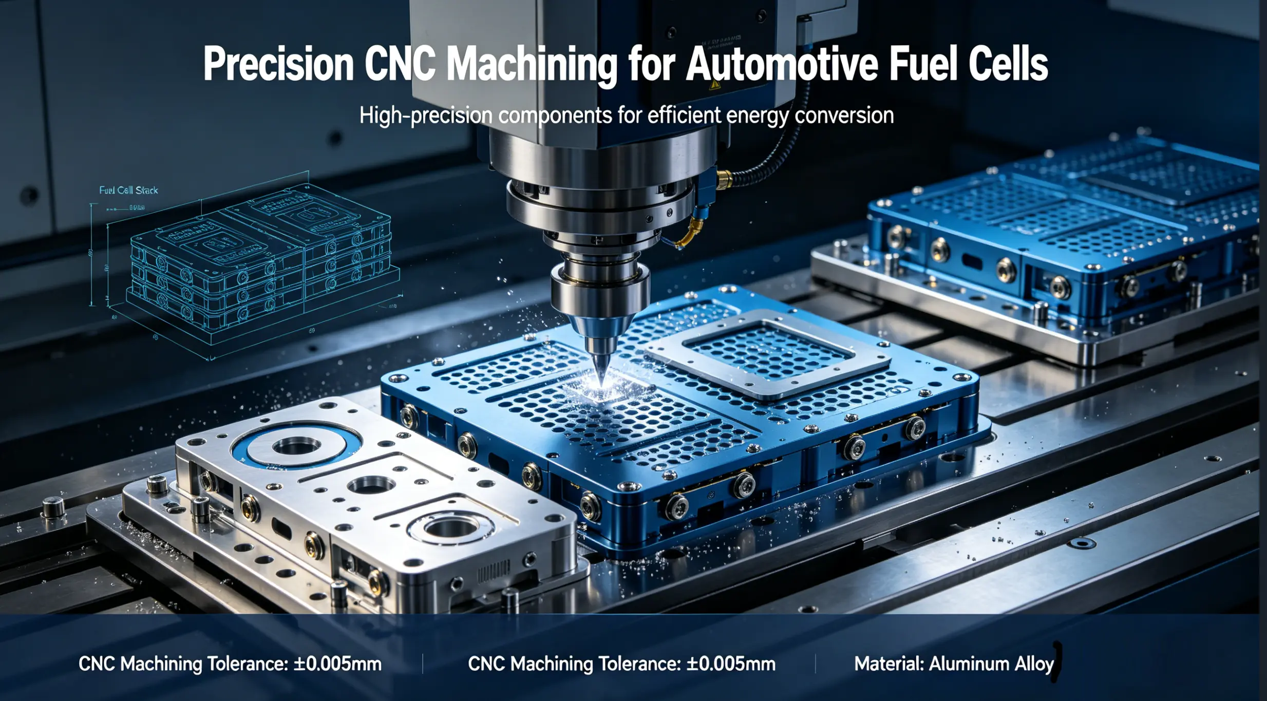
Precision CNC Machining for Automotive Fuel Cells: Components, Materials, and Manufacturing Challenges
Automotive hydrogen fuel cells depend on precision CNC machined components: bipolar plates with flow channels held to ±0.003 in., end plates machined flat to within 0.001 in., and manifold blocks with ±0.0005 in. bore tolerances. Materials include 316L stainless steel, titanium, graphite composites, and aluminum 6061-T6. The challenge is balancing ultra-thin wall sections (0.1-0.3 mm on bipolar plates) with corrosion resistance and electrical conductivity. CNC machining handles prototypes and low-to-mid volume production; stamping takes over above 50,000 units/year.
The hydrogen fuel cell market for automotive applications is projected to grow past $35 billion by 2030 (according to multiple industry forecasts), and every fuel cell electric vehicle (FCEV) rolling off the line depends on precision CNC machined components at its core. Not just any precision; fuel cell components operate in an electrochemical environment where a surface finish that's 0.5 µm too rough increases contact resistance enough to measurably reduce stack efficiency.
Precision CNC machining for automotive fuel cells covers the production of bipolar plates (the highest-volume component in a fuel cell stack), end plates, manifold blocks, humidifier housings, coolant distribution plates, and balance-of-plant fittings. Each component has unique geometry, material, and tolerance requirements driven by the electrochemistry happening inside the stack.
This guide covers exactly which components need CNC machining, which materials work (and which fail), the tolerances that actually matter for stack performance, and the practical manufacturing decisions that separate functional fuel cell hardware from expensive scrap.
How Does a Hydrogen Fuel Cell Work (and Where Does CNC Machining Fit)?
A proton exchange membrane (PEM) fuel cell converts hydrogen and oxygen into electricity, water, and heat. The core unit is a single cell: two bipolar plates sandwiching a membrane electrode assembly (MEA). Hydrogen flows through channels on the anode plate, oxygen through channels on the cathode plate, and the MEA in between catalyzes the electrochemical reaction.
A fuel cell stack is 200-400 of these cells clamped together between two end plates with tie rods providing compression. The stack produces 80-120 kW in a typical passenger FCEV.
CNC machining enters the picture at multiple points:
Bipolar plates (prototyping and low-volume): the flow channels that distribute hydrogen, oxygen, and coolant across the MEA surface are either CNC milled into graphite composite plates or stamped into thin metal sheets. CNC milling dominates at volumes below 10,000 units/year. Above that, stamping becomes economical.
End plates (all volumes): the structural bookends of the stack that distribute compression force evenly. These are CNC machined from aluminum 6061-T6 or stainless steel, typically 15-25 mm thick, with flatness requirements of 0.001 in. or better across the full face.
Manifold blocks and distribution headers: route hydrogen, air, and coolant to the correct channels. Machined from 316L stainless or aluminum with internal passages, O-ring grooves (±0.001 in. on groove width), and sealing faces.
Humidifier and heat exchanger components: maintain membrane hydration and thermal management. Complex internal geometry that often requires 5-axis CNC machining to reach all features in a single setup.
Which Components Need Precision CNC Machining?
Not every fuel cell part needs CNC. Here's a practical breakdown of which components benefit from CNC machining and which are better served by alternative processes.
Component
CNC Machining Role
Typical Material
Key Tolerance
Volume Threshold
Alternative Above Threshold
Bipolar plates (graphite)
Primary process: mill flow channels
Graphite composite
±0.003 in. on channel depth/width
Below 10,000/yr
Compression molding
Bipolar plates (metal)
Prototyping; secondary ops on stamped plates
316L SS, titanium
±0.05 mm (stamped); ±0.025 mm (CNC)
Below 5,000/yr
Progressive die stamping
End plates
Primary process: all volumes
Aluminum 6061-T6
0.001 in. flatness
All volumes
CNC remains primary
Manifold blocks
Primary process: all volumes
316L SS, aluminum
±0.0005 in. on bores
All volumes
CNC remains primary
Coolant distribution plates
Primary or secondary process
Aluminum, 316L SS
±0.001 in. on sealing faces
Below 20,000/yr
Die casting + CNC finish
Humidifier housings
Primary process
316L SS, titanium
±0.002 in. general
Below 15,000/yr
Investment casting + CNC
Current collector plates
Secondary: surface finishing after forming
Copper, gold-plated copper
Ra < 0.8 µm contact surface
All volumes
CNC finishing on all
Tie rods and compression hardware
Standard CNC turning
4140 steel, stainless
±0.002 in. on threads
All volumes
CNC remains primary
The pattern: CNC machining is the primary process for structural and manifolding components at all volumes. For bipolar plates (the highest-volume component), CNC dominates prototyping and low-volume but gives way to stamping or molding at production scale.
What Materials Are Used for Fuel Cell CNC Components?
Material selection in fuel cells is driven by four requirements that rarely align neatly: electrical conductivity, corrosion resistance in acidic environments (pH 2-3 inside a PEM cell), hydrogen compatibility, and weight.
316L Stainless Steel (per ASTM A240)
The most common metal for bipolar plates and manifold blocks. 316L has adequate corrosion resistance in the PEM environment, good formability for stamping, and acceptable electrical conductivity. The "L" (low carbon, 0.03% max) is essential; standard 316 sensitizes at grain boundaries during welding or prolonged heat exposure, leading to intergranular corrosion in the acidic fuel cell environment.
Machining note: 316L work-hardens. Use sharp carbide inserts, maintain consistent chip load (never let the tool rub), and avoid interrupted cuts where possible. For bipolar plate flow channels, high-speed machining at 300-500 SFM with 0.002-0.004 in./tooth feed rate produces the best channel wall quality.
The downside: bare 316L doesn't meet the DOE 2025 target for contact resistance (<10 mΩ·cm² at 1.4 MPa). Most 316L bipolar plates require a conductive coating (titanium nitride, diamond-like carbon, or gold flash on contact areas) after machining.
Titanium Alloys (Grade 1 CP Ti, Ti-6Al-4V)
Titanium offers the best corrosion resistance of any bipolar plate metal (metal ion dissolution <0.1 ppm in PEM conditions) and can achieve contact resistance <20 mΩ·cm² with TiN coating. It's lighter than stainless (4.5 g/cm³ vs 8.0 g/cm³), which matters in automotive applications where stack weight directly affects vehicle range.
The trade-off: titanium costs 5-8x more than 316L per kg and machines 40-50% slower due to its low thermal conductivity (heat concentrates at the cutting edge). For bipolar plates, titanium is typically reserved for premium FCEVs or applications where the weight savings justify the cost premium.
Graphite Composites
Graphite bipolar plates use a resin-bonded graphite composite that is CNC milled to create flow channels. Graphite has excellent corrosion resistance and low contact resistance (10-15 mΩ·cm²) without any coating. The problem is brittleness: graphite plates need minimum wall thickness of 0.5-0.8 mm (compared to 0.1-0.3 mm for stamped metal plates), which makes graphite stacks significantly thicker and heavier.
Machining note: graphite machines easily but creates abrasive dust that accelerates way and linear guide wear. Dedicated graphite machining cells with sealed enclosures, vacuum extraction, and filtered coolant are standard practice. Diamond-coated carbide tools last 3-5x longer than uncoated carbide on graphite.
Aluminum 6061-T6
The standard for end plates, manifold blocks, and structural components. Aluminum machines fast, has excellent thermal conductivity (for heat management), and is lightweight. It is not used for bipolar plates because bare aluminum corrodes in the PEM environment and aluminum oxide is not electrically conductive.
For end plates, 6061-T6 is hard-anodized (Type III, 0.002 in. build-up) for corrosion protection. Critical: hard anodize is non-conductive, so electrical grounding paths must be masked during anodizing or mechanically exposed afterward.
What Tolerances Matter Most for Fuel Cell Performance?
Not all tolerances on a fuel cell component affect stack performance equally. Here are the dimensions that actually matter, and why.
Flow channel depth and width (bipolar plates): ±0.003 in. (±0.075 mm)
Channel geometry directly controls reactant gas distribution and water management. Channels too shallow restrict gas flow and cause starvation at the MEA. Channels too deep waste plate thickness and reduce structural rigidity. Typical channels are 0.5-1.5 mm deep and 1-3 mm wide. Consistency across all 200-400 plates in a stack matters more than absolute accuracy on any single plate; a stack with mixed channel depths produces uneven current distribution.
End plate flatness: 0.001 in. (0.025 mm) across full face
The end plates compress the entire stack. A high spot on the end plate creates localized over-compression that damages the MEA, while a low spot causes under-compression that increases contact resistance. For a typical 300 mm x 150 mm end plate, achieving 0.001 in. flatness requires stress-relieving the aluminum billet before machining and taking light finishing passes (0.002-0.005 in. depth of cut) to avoid inducing residual stress.
O-ring groove dimensions: ±0.001 in. on width, ±0.0005 in. on depth
Every sealing interface in the stack (hydrogen, air, coolant) uses O-ring or gasket seals. The groove depth controls O-ring compression percentage (typically 15-25% of cord diameter). Too little compression leaks hydrogen (a safety hazard). Too much compression damages the O-ring and causes premature failure. These are arguably the most critical CNC features on manifold components.
Sealing face surface finish: Ra 0.4-0.8 µm (16-32 µin.)
Gasket and O-ring sealing faces need controlled surface finish. Too smooth (Ra <0.2 µm) and elastomer seals can't grip the surface. Too rough (Ra >1.6 µm) and micro-leak paths form across the seal interface. This is one case where "smoother is better" doesn't apply; the finish spec has both an upper and lower bound.
CNC Machining vs Stamping for Bipolar Plates: When Does Each Make Sense?
This is the most common manufacturing decision in fuel cell production. Both processes work. The question is volume.
Factor
CNC Machining
Stamping (Progressive Die)
Tooling cost
$0 (no dedicated tooling)
$50,000-200,000 per die set
Per-plate cost (metal)
$15-50 per plate
$1-5 per plate
Per-plate cost (graphite)
$8-25 per plate
N/A (graphite can't be stamped)
Lead time for first parts
3-7 days
8-16 weeks (die build)
Channel depth tolerance
±0.025 mm (±0.001 in.)
±0.050 mm (±0.002 in.)
Surface finish achievable
Ra 0.4-1.6 µm
Ra 1.0-3.2 µm
Design iteration cost
Low (program change only)
High (new die or die modification)
Breakeven volume (metal plates)
Below ~5,000-10,000 plates/yr
Above ~10,000-50,000 plates/yr
Material options
All (graphite, metal, titanium)
Metal only (316L SS, Ti foil)
Minimum plate thickness
0.5 mm (graphite), 0.3 mm (metal)
0.05-0.1 mm (metal foil)
Practical guidance: If you're developing a new fuel cell stack, start with CNC machined plates. The design will change 5-10 times before it's locked. Each iteration on CNC costs a program update; each iteration on a stamping die costs $10,000-50,000 in die modifications and 4-6 weeks of lead time. Once the design is frozen and validated, transition to stamping for production volumes above 10,000 plates/year.
For graphite bipolar plates, CNC milling remains the production process even at higher volumes because graphite composite cannot be stamped. Compression molding (using heated dies to press graphite powder/resin into plate shape) is the high-volume alternative, but it requires $100,000+ tooling investment and is only justified above 50,000+ plates/year.
What Coatings and Surface Treatments Do Fuel Cell CNC Parts Need?
Bare metal surfaces in a PEM fuel cell environment corrode. Every metallic component that contacts the acidic electrolyte or humidified gas streams needs a protective coating that also maintains (or improves) electrical conductivity.
Titanium Nitride (TiN) coating: The most common bipolar plate coating. Applied by PVD (physical vapor deposition) in a 1-3 µm layer. Reduces contact resistance on 316L stainless to <20 mΩ·cm² while providing corrosion protection. CNC-machined or stamped plates must be cleaned and degreased before coating; machining residues (cutting fluid, metal fines) interfere with coating adhesion.
Diamond-Like Carbon (DLC): Higher corrosion resistance than TiN, with contact resistance <15 mΩ·cm². More expensive and limited to flat or gently curved surfaces. Used on premium automotive stacks where long-term durability (>5,000 hours) is prioritized.
Gold plating (selective): Applied only to contact points (lands between channels) for minimum resistance (<10 mΩ·cm²). The gold layer is thin (0.25-0.5 µm) but effective. Cost-prohibitive for full-surface coverage but practical when applied selectively by masking.
Hard anodize (Type III) for aluminum components: Provides corrosion protection on end plates and manifold blocks. Non-conductive: 0.002 in. build-up. Design the component so electrical grounding paths bypass the anodized surface, or mask specific areas before anodizing.
Passivation (ASTM A967) for 316L components: Removes free iron from machined surfaces and restores the chromium oxide passive layer. Required on every 316L fuel cell component. A skipped passivation step on a manifold block can introduce iron contamination into the coolant loop, which eventually poisons the MEA catalyst (irreversible performance degradation).
How to Get Fuel Cell Components Quoted for CNC Machining
Fuel cell components are niche, and not every CNC shop understands the application. Here's what to include in your RFQ to get accurate pricing:
1. Specify the operating environment. "This part contacts humidified hydrogen at 80°C and pH 2.5" tells the machinist why you specified 316L and not 304, and why passivation isn't optional.
2. Call out functional tolerances explicitly. Channel depth ±0.003 in. on the bipolar plate, O-ring groove depth ±0.0005 in. on the manifold, flatness 0.001 in. on the end plate. Don't apply blanket tight tolerance; it inflates cost on non-functional features.
3. Specify surface finish with both upper and lower bounds. "Ra 0.4-0.8 µm on sealing faces" is more useful than "smooth finish."
4. Include coating/treatment requirements in the drawing package. TiN coating, DLC, passivation, hard anodize with masking instructions. These affect dimensional planning (coatings add thickness) and supplier selection.
5. State your volume and program timeline. "50 prototype plates now, 500/month in 12 months" helps the supplier plan. A CNC quote for 50 pieces looks very different from a quote for 50,000 pieces that should actually be stamped.
FlagShip's CNC machining services support fuel cell component production from prototype through low-volume manufacturing, with IATF 16949 automotive quality certification and tolerances to ±0.0001 in. on precision features. Upload your CAD file to get DFM feedback and an instant quote.
Frequently Asked Questions
What is precision CNC machining for automotive fuel cells?
It's the production of fuel cell stack components (bipolar plates, end plates, manifold blocks, coolant distribution plates) using computer-controlled cutting tools. These components require tight tolerances (±0.0005 to ±0.003 in.), biocompatible/corrosion-resistant materials (316L stainless, titanium, graphite), and controlled surface finishes that directly affect fuel cell electrochemical performance.
What materials are used for CNC machined fuel cell parts?
316L stainless steel for bipolar plates and manifolds (good corrosion resistance, needs TiN or DLC coating for low contact resistance). Titanium Grade 1 or Ti-6Al-4V for premium bipolar plates (best corrosion resistance, 5-8x material cost vs stainless). Graphite composite for CNC-milled bipolar plates (excellent conductivity, brittle). Aluminum 6061-T6 for end plates and structural components (lightweight, needs hard anodize).
When should I use CNC machining vs stamping for bipolar plates?
CNC machining for volumes below 5,000-10,000 plates per year, design iteration phases, graphite plates, and titanium plates. Stamping for volumes above 10,000-50,000 plates per year with frozen designs in 316L stainless or titanium foil. CNC has zero tooling cost and 3-7 day lead time. Stamping requires $50,000-200,000 tooling and 8-16 weeks for die build.
What tolerances do fuel cell components require?
Bipolar plate flow channels: ±0.003 in. on depth and width. End plate flatness: 0.001 in. across full face. O-ring grooves: ±0.001 in. width, ±0.0005 in. depth. Sealing face finish: Ra 0.4-0.8 µm (both upper and lower bound). Manifold bore diameters: ±0.0005 in. for press-fit fittings.
What coatings do CNC machined fuel cell parts need?
316L stainless plates need TiN (contact resistance <20 mΩ·cm²), DLC (<15 mΩ·cm²), or selective gold plating (<10 mΩ·cm²) to meet conductivity targets. Aluminum end plates need Type III hard anodize for corrosion protection (non-conductive, so mask grounding paths). All 316L parts need ASTM A967 passivation after machining. Skipping passivation risks iron contamination of the MEA catalyst.
How much do CNC machined bipolar plates cost?
Metal bipolar plates: $15-50 per plate for CNC machined, $1-5 per plate for high-volume stamping. Graphite composite plates: $8-25 per plate CNC milled. The crossover point where stamping becomes cheaper is typically 5,000-10,000 plates per year, depending on plate complexity and material. Tooling amortization on the stamping die ($50,000-200,000) is the main factor.
What automotive quality standards apply to fuel cell CNC machining?
IATF 16949 is the primary automotive quality management standard. SAE J2719 covers hydrogen fuel system materials and components. ISO 14687 specifies hydrogen fuel quality (relevant for contamination control during manufacturing). DOE technical targets set performance benchmarks for bipolar plates: <$3/kW cost, >5,000 hours durability, and contact resistance <10 mΩ·cm² at 1.4 MPa.
Can FlagShip machine fuel cell prototypes with automotive certification?
Yes. FlagShip holds IATF 16949:2016 (automotive quality), ISO 9001:2015, and offers CNC machining with tolerances to ±0.0001 in. Fuel cell prototype bipolar plates, end plates, and manifold blocks can be produced with 3-7 day lead times, with full material traceability and CMM inspection reports.
 Penny Pan
Published Date: 2026/4/24
Penny Pan
Published Date: 2026/4/24